3. Quick Start
3.1. Prepare Hardware
3.1.1. Serial Board
The serial board is mainly used for USB to serial port conversion. The serial board is shown in the figure below, with the labeled positions functioning as follows:
Position 1: Needs to be short-circuited; after short-circuiting, the DUT will enter RF test mode upon power-on
Position 2: Power switch for the DUT module
Position 3: USB interface connected to the computer
Position 4: UART interface, needs to be connected to the DL UART of the DUT module
Position 5: USB interface connected to the computer, same function as Position 3
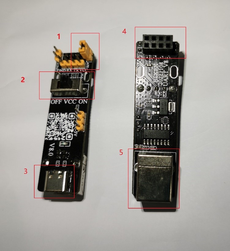
Serial Board
3.1.2. RF Tester (TESTER)
The RF Tester is used to calibrate the RF performance of the DUT module. Hereinafter referred to as TESTER. As shown in the figure below, the labeled positions function as follows:
Position 1: USB interface connected to the computer
Position 2: Interface connected to the SMA connector of the DUT module
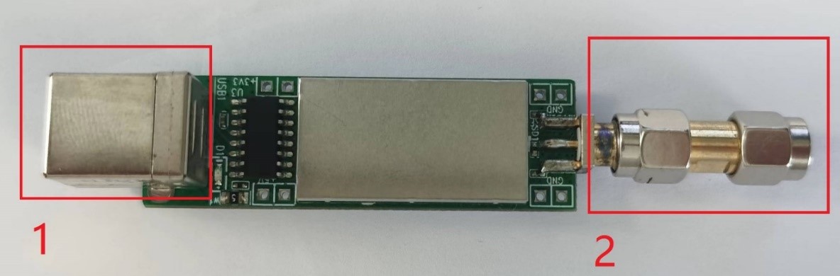
RF Tester
3.1.3. DUT Module or Development Board (DUT)
The DUT module or development board is the device under test, hereinafter referred to as DUT. As shown in the figure below, the labeled positions function as follows:
Position 1: UART interface, used to connect to Position 4 of the serial board
Position 2: RF port, used to connect to Position 2 of the TESTER
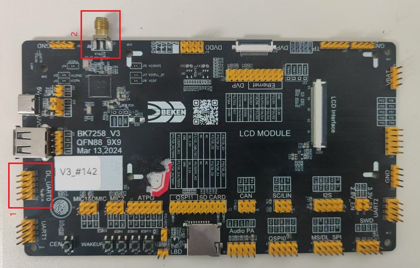
DUT
3.2. Hardware Connection
The hardware connection diagram is shown below.
        flowchart LR
    PC["PC"] -->|"UART Cable"| DUT["Beken Module / Dev Board"]
    PC -->|"USB Cable"| TESTER["RF Tester"]
    DUT -->|"RF Cable"| TESTER
Hardware Connection Diagram
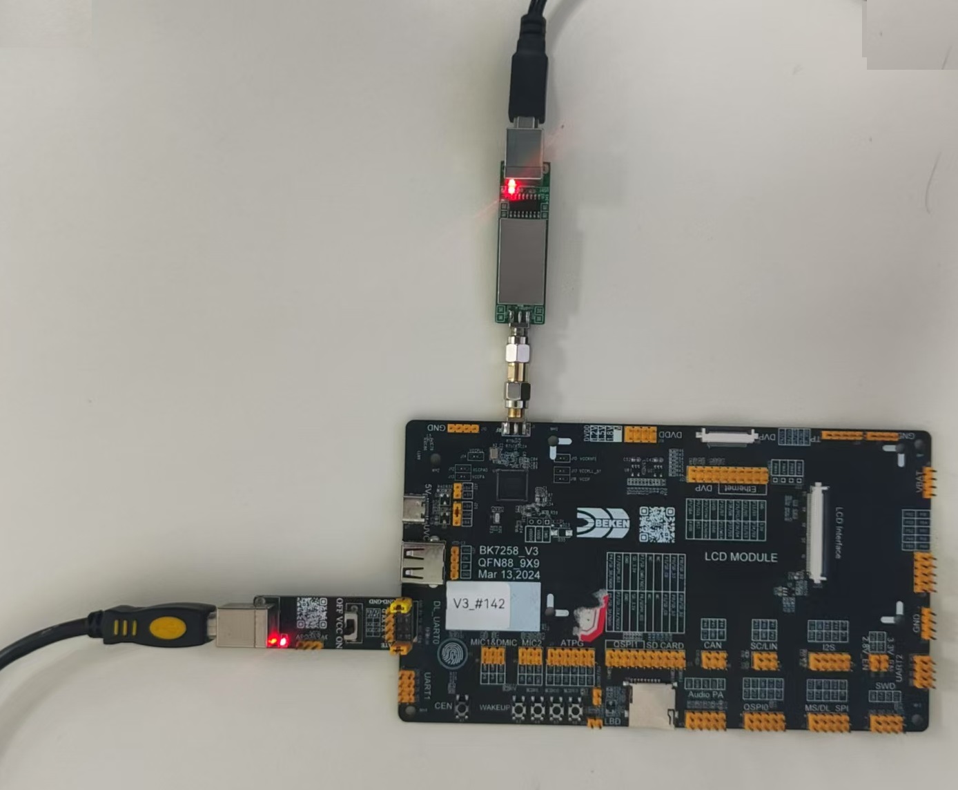
3.2.1. Connect the Serial Board, TESTER, and DUT
After connection, it appears as shown in the figure below.
3.2.2. Connect the TESTER and Serial Board to the Computer USB Ports
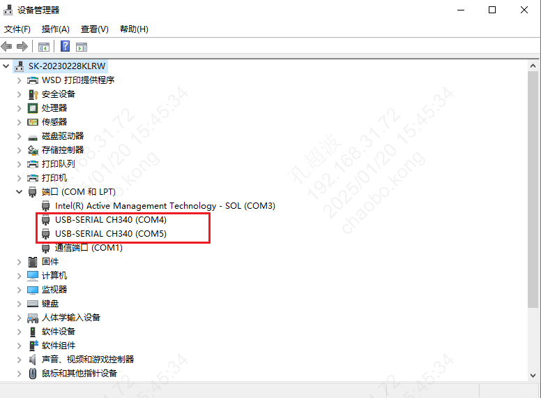
After connection, the corresponding ports can be seen in the Device Manager, as shown in the figure below.
3.3. Software Configuration
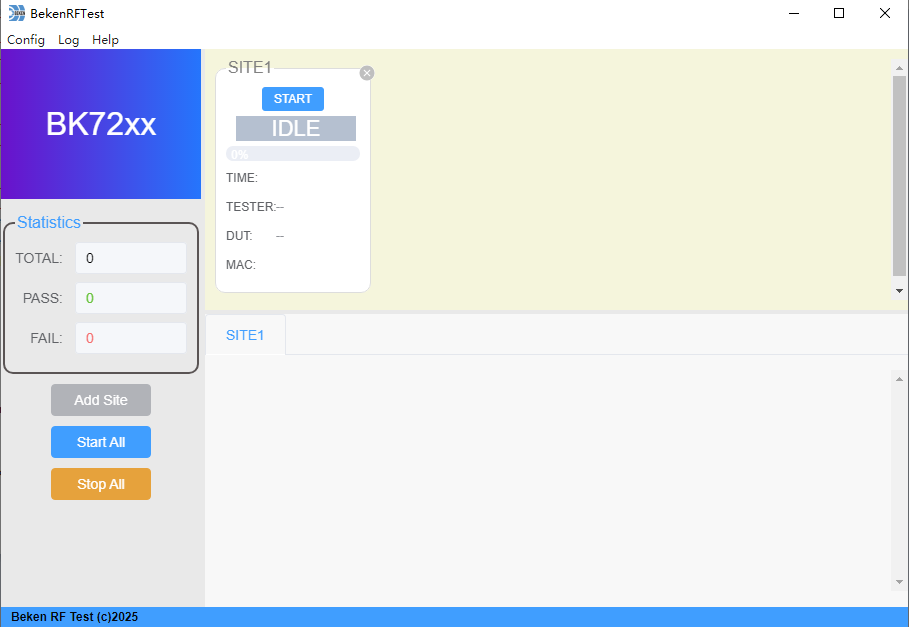
3.3.1. Add Test Site (SITE)
Click the “Add Site” button, and a new SITE will be added on the right side of the tool window, as shown in the figure below.
3.3.2. Configure SITE Information
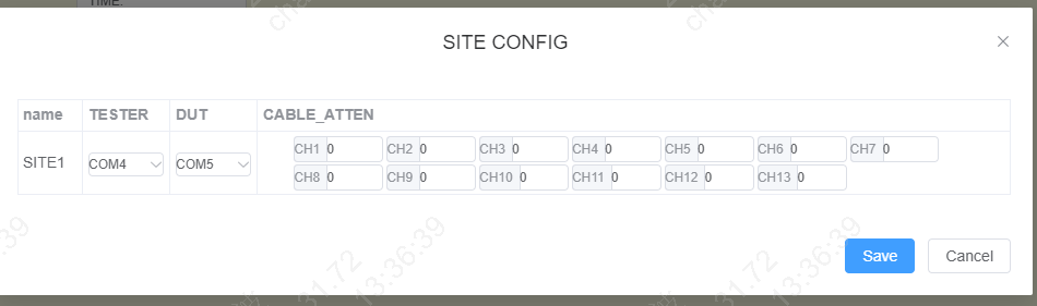
Click “Config” => “Site Config” in the menu bar, and configure the SITE in the popup configuration window.
This includes:
TESTER: Select the serial port number for the RF Tester board
DUT: Select the serial port number for the DUT module/development board
ATTEN: Set the cable loss for corresponding channels, default is 0
3.3.3. Select Chip and Set MAC
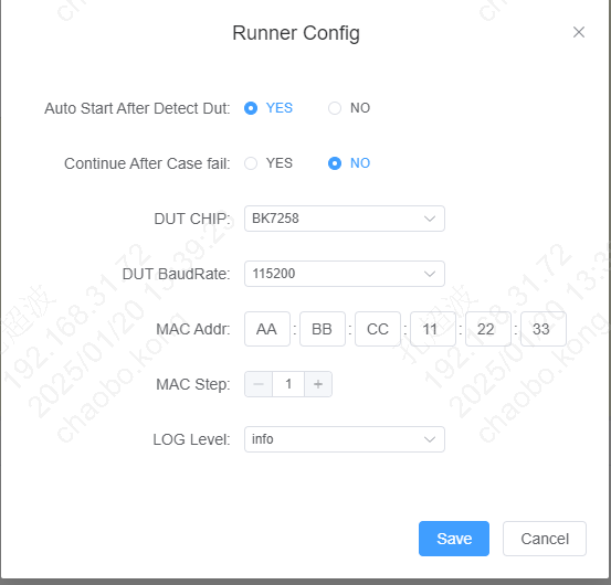
Click “Config” => “Runner Config” in the menu bar, and configure in the popup window.
DUT CHIP: Select the DUT chip type
MAC Addr: Enter the Wi-Fi MAC address
3.4. Run Test
Click “START” or “START ALL” to begin testing.
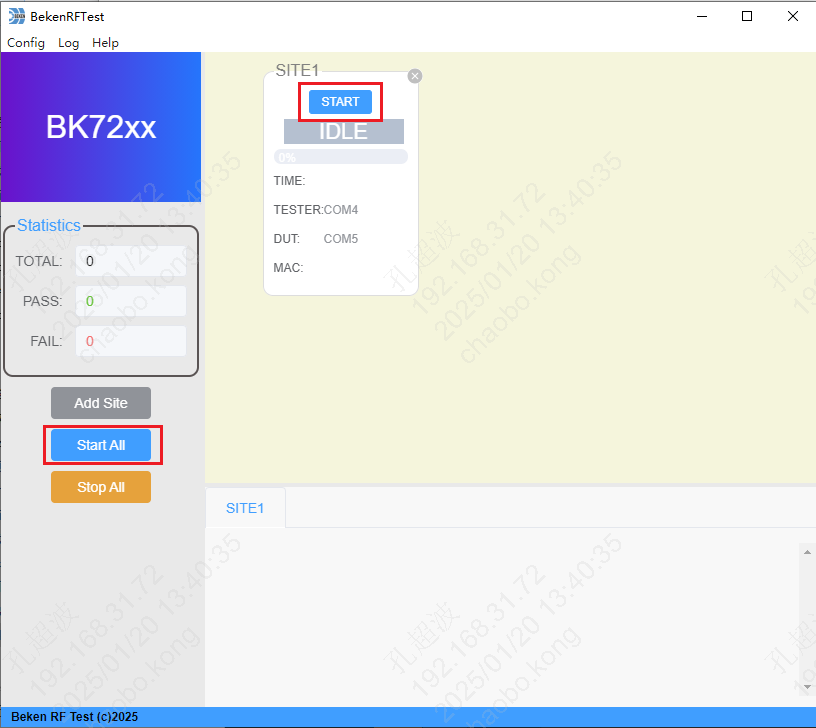
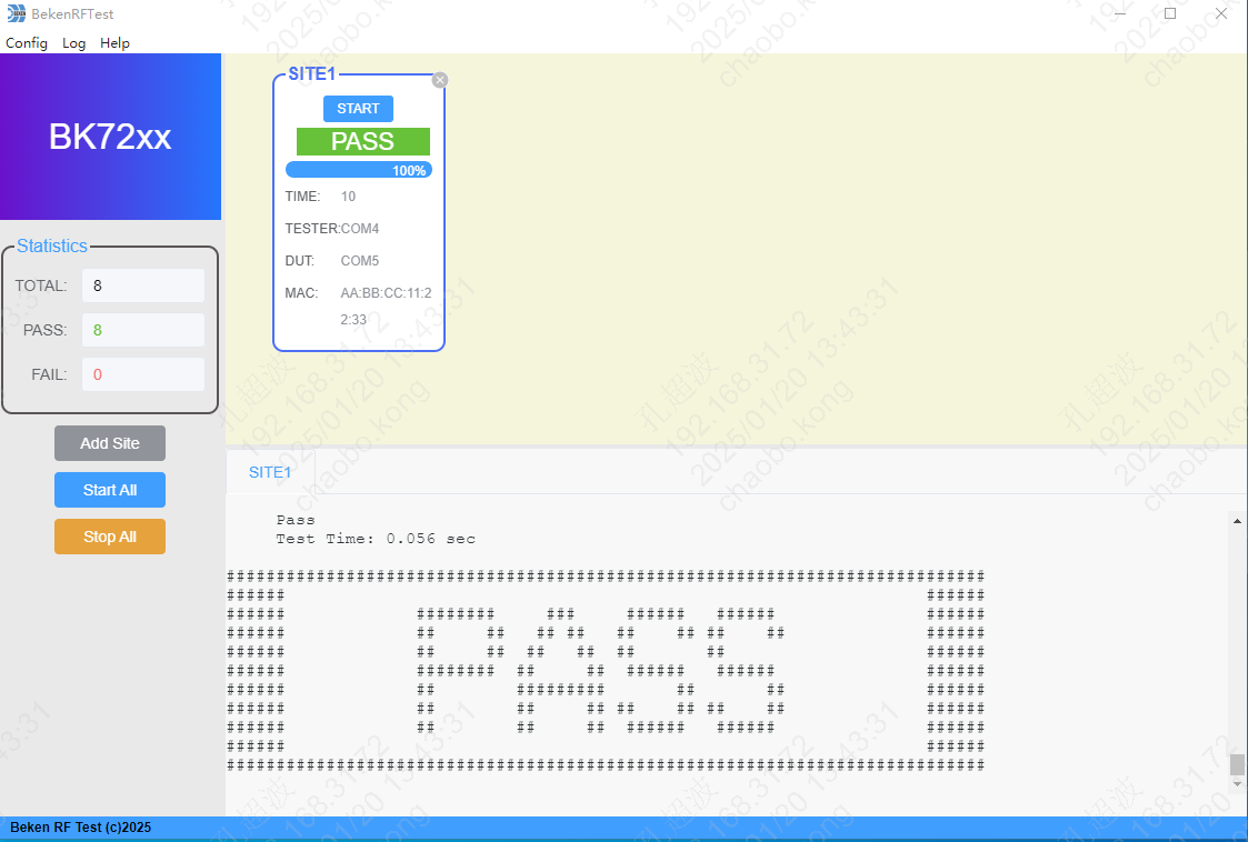
After the test is completed, the interface will display the test results and log information generated during the test.