4. Test Configuration
BekenRFTest provides users with flexible configuration options to meet diverse testing requirements through different configurations.
4.1. Site Config
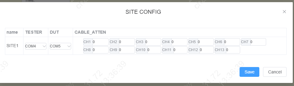
In the menu bar, “Config” ==> “Site Config” opens the corresponding configuration dialog. You can configure the Tester/DUT serial port numbers for each SITE and the cable loss values for each channel.
4.2. Runner Config
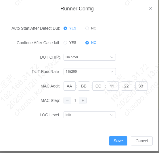
In the menu bar, “Config” ==> “Runner Config” opens the corresponding configuration dialog.
Auto Start After Detect Dut: “YES” means that after starting test execution, connecting a DUT will automatically begin testing (supported on Windows 10 and above)
Continue After Case fail: “YES” means that if a test case fails during testing, subsequent cases will continue to execute
DUT CHIP: Select the DUT chip type
DUT BaudRate: Select the DUT serial port baud rate
MAC Addr: MAC address. During testing, a MAC address will be written to the DUT. This configuration item sets the starting MAC address
MAC Step: MAC address increment step
LOG LEVEL: Select the log level
Note
During testing, a MAC address will be written to the DUT. Each time a test is executed, the MAC address value will be incremented according to the MAC Step value, ensuring that a unique MAC address is written to each module/development board.
4.3. Freq Calibrate Config
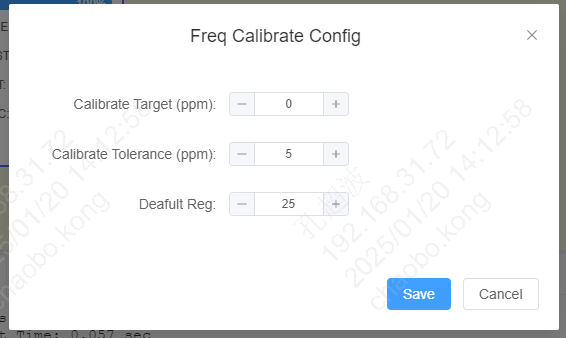
In the menu bar, “Config” ==> “Freq Calibrate Config” opens the corresponding configuration dialog. This configuration page mainly configures parameters related to frequency offset calibration testing.
Calibrate Target (ppm): Frequency offset calibration target value, in ppm, where 1ppm is approximately 2.4kHz
Calibrate Tolerance (ppm): Frequency offset calibration tolerance value. During calibration, when the frequency offset is between (target - Tolerance) and (target + Tolerance), calibration is considered complete
Default Reg: Default crystal value, recommended to keep the default value
Note
The frequency offset calibration process involves continuously adjusting the crystal value. The closer the default crystal value is to the final calibrated value, the shorter the calibration time. This tool has set a relatively reasonable default value for different chip platforms. During actual testing, if you find that frequency offset calibration takes too long, you can refer to the log information to find the final calibrated value (the value in the CAL column of the FREQ_CALIBRATION CASE) and modify the “Default Reg” parameter accordingly.
4.4. Power Calibrate Config
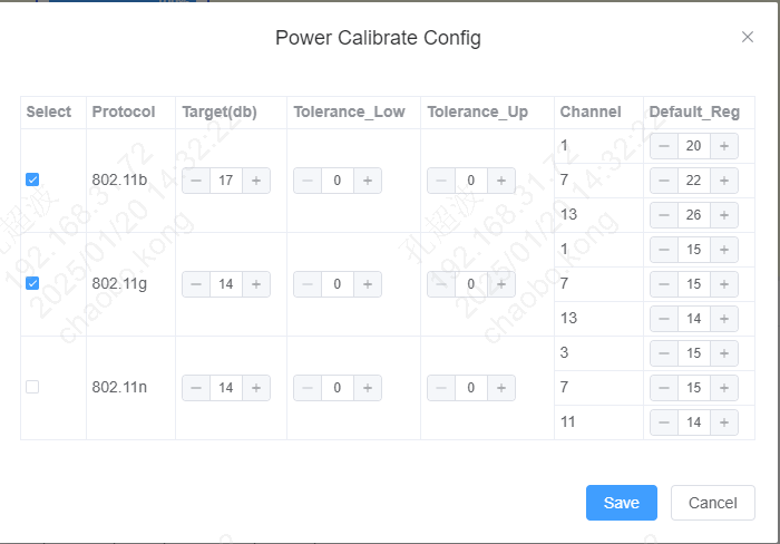
In the menu bar, “Config” ==> “Power Calibrate Config” opens the corresponding configuration dialog. This configuration page mainly configures parameters related to power calibration testing.
Target(db): Power calibration target value
Tolerance_Low/Tolerance_Up: Power calibration tolerance values. During calibration, when the power value is between (Target - Tolerance_Low) and (Target + Tolerance_Up), calibration is considered complete
Default Reg: Default crystal value for the corresponding calibration channel, recommended to keep the default value
Note
The Default Reg setting recommendation is similar to “Freq Calibrate Config”.
4.5. TX Verify Config
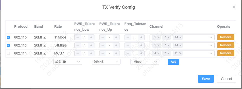
In the menu bar, “Config” ==> “TX Verify Config” opens the corresponding configuration dialog. This configuration page mainly configures parameters related to frequency offset/power TX verification testing.
PWR_Tolerance_Low/PWR_Tolerance_Up: Power tolerance values. When the test power value is between (Target - Tolerance_Low) and (Target + Tolerance_Up), the test is considered PASS. The Target value refers to the note information below
Freq_Tolerance: Frequency offset tolerance value. During testing, when the frequency offset is between (Target - Freq_Tolerance) and (Target + Freq_Tolerance), the test is considered PASS. The Target value is the Calibrate Target (ppm) parameter in the “Freq Calibrate Config” configuration
Channel: Select which channels to perform verification on
Note
In power verification, the Target value is calculated based on the “Target(db)” in the “Power Calibrate Config” configuration, with different Rate values applied. The calculation formula is (“Target(db)” + “offset” * 0.25). The offset values for different Protocols are shown in the tables below.
Rate |
11M |
5.5M |
2M |
1M |
offset |
0 |
0 |
0 |
0 |
Rate |
54M |
48M |
36M |
24M |
18M |
12M |
9M |
6M |
offset |
0 |
2 |
2 |
2 |
3 |
3 |
4 |
4 |
Rate |
MCS7 |
MCS6 |
MCS5 |
MCS4 |
MCS3 |
MCS2 |
MCS1 |
MCS0 |
offset(20MHZ) |
0 |
2 |
2 |
2 |
3 |
3 |
4 |
4 |
offset(40MHZ) |
0 |
0 |
0 |
0 |
0 |
0 |
0 |
0 |
4.6. Test Case Configuration
You can add or remove test cases by modifying the CASE_LIST.yaml file in the case_config directory.
Taking the BK7258 configuration as an example, the following test cases will be executed in order:
SET_DEST_POWER
FREQ_CALIBRATION_LIMIT
POWER_CALIBRATION_LIMIT
SAVE_CALIBRATION_DATA
TX_VERIFY_CASE
ENABLE_CALIBRATION_FLAG
WRITE_MAC
It is recommended to keep the default configuration for testing.
# Test Case Configuration Table
-
  CHIP: [BK7236, BK7258, BK7259, BK7236N]                    # Chip list for this configuration
  CASE:
    - SET_DEST_POWER                        # Set target power
    - FREQ_CALIBRATION_LIMIT                # Frequency offset calibration
    - POWER_CALIBRATION_LIMIT               # Power calibration
    - SAVE_CALIBRATION_DATA                 # Save calibration data to flash
    - TX_VERIFY_CASE                        # TX verification (including frequency offset and power verification)
    - ENABLE_CALIBRATION_FLAG               # Enable calibration flag
    - WRITE_MAC                             # Write MAC address
-
  CHIP: [BK7235, BK7256, BK7231N, BK7238, BK7252N]  # Chip list for this configuration
  CASE:
    - FREQ_CALIBRATION_LIMIT               # Frequency offset calibration
    - POWER_CALIBRATION_LIMIT              # Power calibration
    - SAVE_CALIBRATION_DATA                # Save calibration data to flash
    - TX_VERIFY_CASE                       # TX verification (including frequency offset and power verification)
    - ENABLE_CALIBRATION_FLAG              # Enable calibration flag
    - WRITE_MAC                            # Write MAC address